
7 - Embedded Programming
Intro
The assignment of this week was to read and understand the datasheet of a microcontroller, to program the FabISP and the echoBoard using different techniques.
Reading the ATTiny 44/a datasheet
When you use an electronic component it is very useful to read the datasheet. It contains many information about the characteristics of the components, especially the power requirements (helpful to don't damage the component) and the pinout (useful to correctly connect the component). Moreover the datasheet tell us the behaviour of the component and, if necessary, the configuration parameters (that could be software or hardware). A microcontroller is a complex component so the datasheet is very rich of information. The ATTiny datasheet can be found here.
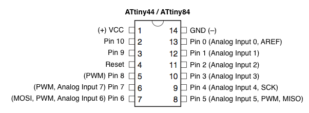
The pinout scheme was very useful to design the circuit of the echoBoard to add the button and the led but also to check the connections and the alimentation. Moreover was also useful to understand the role of the fuses and to know how big could be the program that I can upload into it. Indeed using Arduino IDE means to have a bigger program as it imports libraries (and the bootloader), so sometimes is necessary to optimize the code or writing it in C. According to the datasheet the Attiny44/a has 4K of Flash Memory, 256 bytes of Program Memory and 256 bytes of EEPROM. Then in the datasheet there is a long explanation of all the characteristics of the pins (PORTs) as each pin could do many things (i.e the PA6 works as ADC as SDA and as MOSI, OC1A, PCINT6 (digital I/O with Pin Change Interrupt )). Moreovere are explained also the register to use and read the values of the pins as the Port data register (with the logical values of the pins) and the Data Direction register (to say if a pin is Input or Output)
Programming the Echo Board
To program the Hello board I started by the behaviour to give to it. I decided to make te led light up when I press the button. So I wrote a simple sketch based on the button example(in the Arduino IDE you call the programs "sketches") to turn on the led when I press the button. When programming using the Arduino IDE the pin are addressed with a number. I found a schematic with the right correspondance here (look at the image below). From the schematic I saw that the pin where the button is connected is recognized by Arduino software as pin 3. The pin where the led is connected is recognized by Arduino software as pin 8. Below a useful image of the pinout of the Attiny 44a:
Here is the code:
In the setup() I said to the microcontroller that the pin 3 (button) is used as input and that the pin 8 (led) is used as an output. Then in the loop(), that is the code that is continuosly executed on the microcolntroller, I said to read the logic value of the pin 3 with the command digitalRead(). The value is 0 when the button is notpressed or 1 when is pressed. The with an if statement I check the value and I turn on or off the led according to it using the digitalWrite() command. I found very useful the reference page of the Arduino software.
Using the FabISP as a programmer
To use the FabISP i removed the two jumpers as reported in this very useful tutorial then I gave power to the Echo Board through the FTDI connector. I started using the FabISP to program the Echo Board, however I received many errors, the most common was "target not responding". So to reduce the possible causes of error i used a commercial programmer "usbasp" . It gave me the same error so I checked the board for electrical problems.
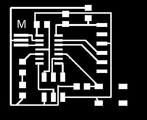
After several attempts of flashing the board I realized that the problem was caused by several short circuits. Indeed a trace underneath the microcontroller was too close to the pads and, after soldering there were unwanted junctions. I used the desoldering wire and the desoldering pump but I wasn't able to fix. So I designed another version of the board with more space between pads and traces adding an extra 0 ohm resistor as a jumper.
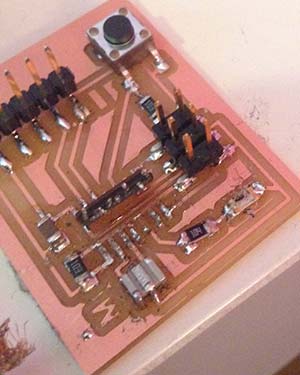
Above the first version of the board. Below the second version. You can download the scheme and the board file for Eagle
After milling and soldering again the board I was able to program it using the Arduino IDE and the usbasp. The ArduinoIDEwas already configured as I already changed the boards.txt. At the beginning i burnt the bootloader using the Arduino IDE. However it doesn't really load the bootloader but just set the fuses. Then
Here is a video of the working board:
Hello Board from Massimiliano Dibitonto on Vimeo.
 Attribution, non-commercial, share alike.